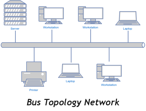
A bus topology is a type of local area network in which nodes (devices or workstations) are connected to a single cable or single backbone. The cable which is used to connect devices is known as coaxial cable or RJ-45 cable.
The problem with bus topology is that if the cable has an issue then the whole network stops working. There may be more than one linear cable in the network for safety purposes. It is a simple type of network topology which is set up easily. Bus topology is also economic to set up.

Bus topology does not need extra cables during installation i.e. it requires a few cables as compared to another type of topologies.
If any node fails in the network then other nodes keep working. It is easy to add new nodes to the network without rearranging other nodes.
Bus topology is not good for long distance networking because some of the data loss may occur. If the nodes are scattered around different directions then bus topology not work in this case and it is better to use mesh topology, ring topology, or star topology.
Bus topology works well for small distance networking. It also requires fewer cables than star network topology. If new devices are added to the bus network then it will slow down the data transfer rate which is a drawback. Also, terminators are needed on both sides of the cable.
If any error occurs in the network then it is difficult to detect and debug the issue.
Examples of a bus topology:
- An example of bus topology is connecting two floors through a single line.
- Ethernet networks also use a bus topology
- In a bus topology, one computer in the network works as a server and other computers behave as clients. The purpose of the server is to exchange data between client computers.
- Printers, scanners and other input/output devices can be added in the office/home by using bus topology network


Leave A Comment